Assignment 2 - The Fuel Tank
Assignment 2 - The Fuel Tank
Emma La Costez5115182
Introduction
Assignment 2 was to create a skin for a Yamaha IT250 motorbike. The material used for the skin was aluminium forming the adhering to to a 1:1 prototype model which was created of the tank. The project called on many techniques including digital making, metal shaping, tool making and many other experimentations to create a succinct form as close to the prototype as possible. The Yamaha IT250 was chosen by our group as it is the most difficult form and shape to replicate out of metal.


Process:
1. The Prototype Model
In order to replicate the fuel tanks skin out of aluminium we needed to create a model as a group which we could use as a measurement device and guide for the shaping of our individual metal pieces.Part 1. Photogrammetry
As a group and with the advice of tutors we decided photogrammetry would be best suited to begin the digital making of our fuel tank prototype. This software allowed us to capture the unique shape and form of the fuel tank which would have been difficult to to model using the other available softwares. using masking tape to provide marking on the model for photos we all took our own pictures (hundreds of pictures) from all different angles. Holding the camera still and rotating the model seemed to be the best technique to capture the shape and form of the YamahaIT250 tank. After many of us trialled our images in photogrammetry we came up with a successful digital prototype of the tank.
The digital process was long and difficult as we were all learning to use new softwares and running into many issues with our photos not resulting with a complete form in the software. However my attempts at photogrammetry although were unsuccessful and not used for our final prototype have left me familiar with the software and eager to implement its use into my landscape architecture studio projects as it can capture unique forms and curved and indented shapes evident by the fuel tank which are often hard to model on pother digital softwares that I previously used for landscapes such as sketchup.

(Image of a failed photogrammetry attempt)

(Image of our successful Photogrammetry outcome)
Part 2. Slicer
- Once the Photogrammetry process was finally over.... and we had a successful template we were able to import it into fusion 360's slicer which was a more familiar software and therefore easier for our group to navigate.
- A group member (Charlie) prepared the model for laser cutting in slicer using the X and Y axis to seperate the shapes of the model in which we could assemble together after laser cutting.
- While preparing to laser cut we used a callipers to check the width of the plywood we would be using for our model. We then realised how many sheets we would need and decided to cut back on the amount of slices and therefore create lager gaps between the pieces we would be fitting together.... However we ran into a few issues figuring out the widths between the slicers on slicer and weather this would be accurate once laser cut.
- To laser cut the templates of our model we needed to export the slicer file into illustrator. Once exported we ran into issues as there were missing gaps in the lines created in slicer and they were also wonky in parts. Therefore we spent time adjusting the line work in illustratrator.
Part 3. Laser Cutting
- Our first cut attempt was unsuccessful. We did not auto focus the laser which meant it was not vertically in the correct position. As well as this the issue we had in slicer being unable to identify the distance between the template pieces was evident as the offset gap we thought we were making is not what turned out.
- We adjusted the offset in slicer ensuring that we left enough room for glue and laser cutting and assembling issues as we were advised by Daniel that if our slots were too wide we could always wet the wood to make it swell up where as if the slots were too small it would mean repeating the laser cutting process again.
- After the cutting of our unsuccessful test piece we calculated that we would need to change the offset on slicer the gaps to 6mm to end with 3.5mm gaps once laser cut.
Luckily our second attempt was successful and gaps were as expected we then continued to cut all the pieces.


Part 4. Assembling the Model
- To assemble the model the individual templates we slotted together with the perfect amount of room. Using wood glue left to dry then finished with a masking tape coating to preserve the wood model when we drew our dividing sections on.
- Our prototype turned out slightly bigger than the original tank as it was the best way to ensure the shapes were as accurate as possible after the photogrammetry process.


2. Dividing the model
Originally we were going to divide our model into three sections side - middle - side. However after considering the techniques we would use to shape our metal based on the knowledge gained from assignment 1 we realised this would probably be impossible well at least extremely difficult. Therefore through careful consideration and advice from tutors we decided to divide our model into 6 sections. The section I was taking care of was the centre/ top.
3. Paper template
Now that the model was created we then needed to create additional paper template over the top to use as a stencil for cutting our metal shapes. This was more difficult than it seemed as the individual pieces of wood were interfering with the shape as a whole and it became difficult identify each section.
4. Preparing the metal Pieces
- Next was tracing the paper template shapes onto the aluminium and cutting our the shape with tin snips. I cut out my aluminium leaving 2mm around the edges for error as I learnt is always a good idea after assessment 1.
- I then used a hole saw on the drill press to cut out the centre hole which took two attempts using two different sized hole saws. After completing my piece I realised that I should have cut out the hole after shaping my metal as it would've allowed more room for shaping.


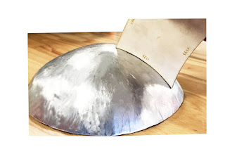
5. Shaping the Metal

- I began by marking on the metal two areas which needed to be bent the most and would form the skeleton of the future metal shaping. I tried using the magna fold to do this which took for ever as I did not know how to use the machine. I used the magna bend to create a slight bend in the lower bend. I used the folder to fold the top bend.

- I then tried curving the metal over the dolly using the steel mallet however ran into many issues as the form of the dolly was not correct for the stage of shaping I was up to.
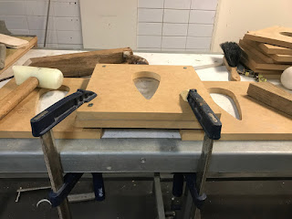
- After struggling to curve my edges I drew on techniques used for the tray exercise. This included using scrap wood to make a template, clamping to metal and shaping around it. I roughly traced the shape of the model that I wanted to curve around onto the scrap wood and used the ban saw to cut it I then sanded the edges to create a rounded finish. I then clamped my metal and wood held pressure on the wood with the end of the dolly and used the rubber and wooden mallets to bend the edges of the metal over.


- The technique was kind of working however I was running into issues as the edges began to fold onto them selves.
- So I decided to use the shrinker to combat the excess metal on the edges which I had folded earlier.I used a test piece on the shrinker first.

- Once I had used the shrinker I was happy with the curved shape it created however it needed to be filed and there were still areas to be further curved.


- So after realising my scrap wood template was not going to achieve the depth of curve that I was after to adhere to the model I created a DYI clamp template.
- I found that the edges of the clamp in the workshop were perfect for the shape I was trying to achieve so I therefore clamped the clamp to heavy steel object and tightly held my metal on top of it and began hitting the edges to curve around it. I used the metal mallet for this as it was the heaviest and shaped it the easiest.

- Once this was done I used the english wheel to flatten out the bottom area then fit to other group members pieces once they were done and refined my curves by hitting softly with he wood hammer on the dolly as well as flipping it over and hitting it lightly in the sandbag to adhere to the model and their pieces.


- I then filed the edges and the inside of the cut out circle and lighting hit some unwanted forms out with the light wooden mallet against the table
- I was happy with the way it fitted onto the model.


- Finally I polished my metal .
-


The Final Product


Our Group Effort

Reflection
Overall this task was an enjoyable process. Being in groups of ten we were able to interact and converse with students from other disciplines and come up with solutions to difficulties which may have been a problem if working on your own. The diversity of our group allowed us to trial a range of softwares ourselves however took some pressure off as there were students who were already familiar with he software such as fusion 360.
This project tested my metal shaping skills gained from the first assessment as I heavily relied on the techniques used for the tray to complete my piece.
Choosing the most difficult tank made the task quite challenging however was worth it. It was interesting to see the pieces all together at the end and watching the other students in my group draw on different techniques to form their shapes.
The complex shape of the YamahaIT250 fuel tank can relate to my area of study as its many subtle curves and concave shapes are relevant to landscape architecture in regards to natural landscapes and my own style where I often turn to organic forms when designing. In particular the design of landscape elements such as furniture and various sculptural elements and installations. I think this task will help me with my future career as a landscape architect as I now have a much better understanding of the forms with make up an object for example at the beginning of the assignment looking at the tank I saw three divisions which made sense to me however I now realise that doe snot make sense at all from a metal shaping perspective.
Comments
Post a Comment